
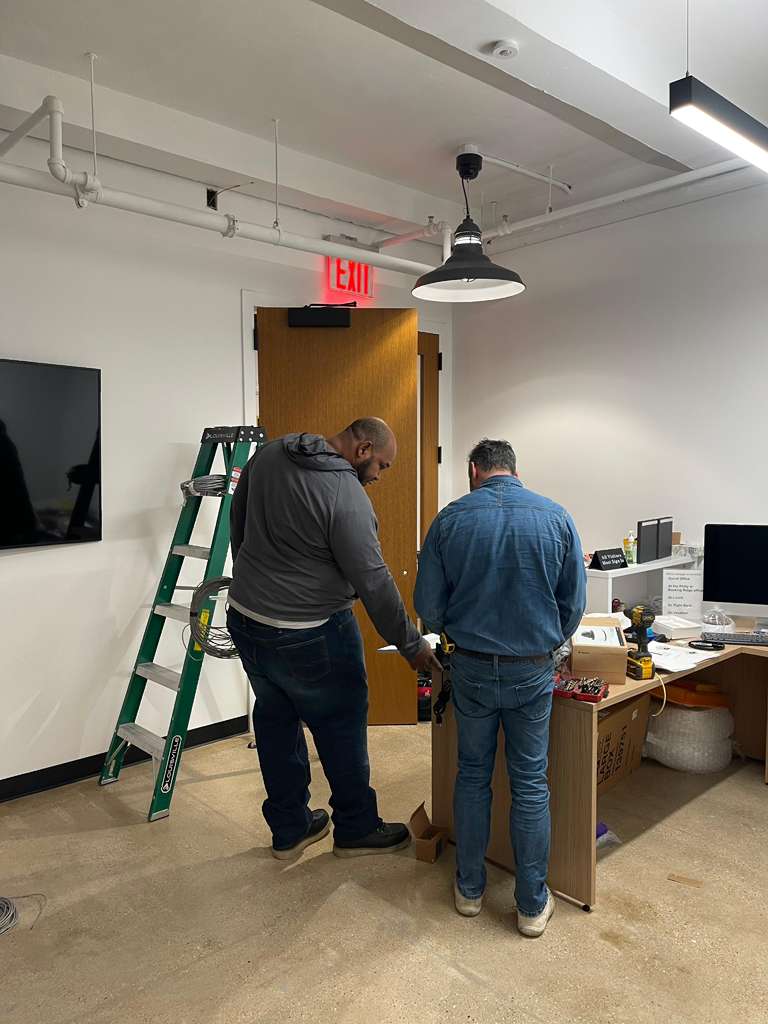
Applying padlocks and danger tags to energy-isolating devices represents only the preliminary phase of a comprehensive hazardous energy control procedure. Securing a breaker handle, turning a valve, or applying a lockout hasp does not guarantee that machinery is safe to service. True operational safety is achieved only when we physically prove that every power source is disconnected, all trapped energy is dissipated, and the equipment cannot reactivate under any operating condition.
Through our extensive work auditing industrial facilities, manufacturing plants, and commercial building infrastructures, we regularly observe that post-lock application checks are the most frequently compromised phase of energy control. According to accident data published under the OSHA 29 CFR 1910.147 Standard, nearly 85 percent of unexpected energy release incidents occur because maintenance teams assumed the lock itself established a zero-energy state. A lock restrains a switch; it does not test circuit continuity, prevent valve bleed-through, or discharge hidden capacitor banks.
We developed this guide to outline our standardized 7-step post-application verification protocol. By integrating these precise physical checks, live-dead-live testing routines, and group lockout procedures, facilities transform a simple locked-out state into a fully verified, zero-energy environment.
Table of Contents
Why Post-Application Verification Is the Most Overlooked Hazard
The primary reason post-lock verification fails in the field is cognitive bias: workers assume that physical attachment of a lock equals absolute safety. However, mechanical devices and electrical disconnects can fail internally without providing any visual indication to the operator.
- Disconnect handles can snap internally, leaving contacts closed while the exterior handle rests in the off position.
- Gate and ball valves can leak internally due to seat degradation, allowing high-pressure fluid or gas to bypass a locked handle.
- Dual-feed equipment and emergency backup circuits can keep secondary control boards energized even when the primary breaker is open.
- Stored potential energy in elevated rams, counterweights, compressed springs, and hydraulic accumulators remains latent until mechanically disturbed.
- Capacitors in variable frequency drives (VFDs) and power supply units retain lethal electrical charges long after main power disengagement.
We treat locks and tags strictly as isolation tools, not test instruments. The 7 steps following lock placement provide the physical proof required before any worker enters a danger zone.
The 7-Step Post-Lockout Verification Protocol
Step 1: Attempt to Operate Equipment via Normal Controls (The Tryout)
Immediately after all authorized padlocks and tags are affixed to the energy-isolating devices, we perform a deliberate tryout using all standard operating controls.
- Press all start buttons, toggle switches, foot pedals, and touchscreen start commands on the local control panel.
- Activate remote start pendants, selector switches, and automated building management system (BMS) controls.
- Hold start switches in the operating position for several seconds rather than giving a brief tap to check for time-delayed relay engagements.
- Visually confirm that zero mechanical motion, audible motor hums, pneumatic valve clicks, or control panel indicator illuminations occur.
- Immediately return all operating controls to the neutral or off position after testing to prevent unexpected start-up if isolation fails during subsequent steps.
If any movement or electrical response occurs during tryout, work must halt instantly. The team must re-trace electrical single-line diagrams and piping schematics to identify missed energy feeds.
Step 2: Verify Isolation of Every Energy Source
A single piece of industrial machinery often depends on multiple energy media. After locking primary isolators, we test every energy line individually at the point of work.
- Electrical Energy: Perform a three-step Live-Dead-Live voltage test using a calibrated digital multimeter or non-contact voltage tester rated for the specific voltage category. Test the meter on a known live source, test phase-to-phase and phase-to-ground across all conductors on the load side of the disconnect, and re-test the meter on the live source to confirm instrument functionality.
- Pneumatic Energy: Open manual line drain valves downstream of the locked disconnect. Observe calibrated pressure gauges until readings drop to absolute zero PSI.
- Hydraulic Energy: Check system pressure gauges across all directional control manifolds, fluid power reservoirs, and high-pressure lines to confirm zero system pressure.
- Chemical and Thermal Energy: Verify double block-and-bleed valve configurations, confirm open vent lines, and measure surface temperatures with infrared thermometers to ensure safe working conditions.
Under NFPA 70E Standard for Electrical Safety in the Workplace guidelines, establishing an electrically safe work condition explicitly requires phase-to-phase and phase-to-ground testing at the precise point of maintenance.
Step 3: Dissipate, Bleed, and Mechanically Restrain Residual Energy
Isolating the primary power feed does not eliminate energy stored within downstream components. Residual energy must be systematically released or physically trapped.
- Discharge high-voltage capacitors in drive cabinets using approved grounding sticks, observing manufacturer-specified discharge wait times (often up to 10 minutes).
- Bleed trapped hydraulic accumulators and compressed air receiver tanks through dedicated, lockable bleed valves.
- Lower elevated machine rams, die sets, and heavy mechanical arms to their lowest resting position, or insert certified mechanical safety pins, drop-bars, or hardwood blocking devices.
- Release spring tension on mechanical actuators, brake assemblies, and valve linkages, manually verifying that no residual mechanical force remains.
- Install safety chain wraps or mechanical valve lockouts on open vent lines to ensure they remain open for the duration of the task.
Step 4: Execute Controlled Group Lockout Verification
When complex maintenance involves multiple authorized workers, a group lockout box or multi-hole hasp protocol must be executed to protect individual crew members.
- The primary authorized employee applies master padlocks to all energy isolating points and places the keys inside a designated group lockout box.
- The primary employee conducts the full tryout and zero-energy verification sequence while representative crew members observe.
- Each authorized team member inspects the isolation points, verifies zero energy independently, and applies their individual safety padlock to the group lockout box.
- No key can be extracted from the group lockout box to unlock energy sources until every single worker has removed their personal padlock from the box.
Step 5: Conduct a Staged Restoration or Controlled Bump Test
For complex machinery, high-voltage electrical switchgear, or newly modified mechanical drives, a controlled functional test provides secondary verification before deep tear-down begins.
- In electrical systems, a qualified electrician wearing appropriate arc flash Personal Protective Equipment (PPE) executes a controlled bump test with panel covers in place to verify switch contact separation.
- In mechanical systems, technicians manually turn drive shafts using turning bars or wrenches (with power isolated) to confirm zero mechanical binding or counterweight resistance.
- Re-verify zero energy state and re-apply all personal locks immediately following any temporary functional check.
Step 6: Maintain Verification Continuity Across Shift Changes
Safety continuity must not break when work extends beyond a single shift. An oncoming shift cannot rely on the previous crew’s verification.
- Departing authorized employees brief incoming staff on all active isolation points, zero-energy test results, and current equipment statuses.
- The incoming authorized worker applies their personal padlock to the group lockout box or hasps before the outgoing worker removes theirs.
- The incoming employee performs a personal tryout and spot-checks critical bleed valves and test points before entering the machinery footprint.
- All shift transfer actions, lock handoffs, and re-verification checks are logged in the facility lockout logbook.
Step 7: Document Verification and Issue the Zero-Energy Permit
Physical verification steps must be recorded on an official Energy Control Permit to establish accountability and maintain an auditable compliance trail under guidelines supported by research from the NIOSH Hazardous Energy Program.
- Complete the permit checklist, noting specific multimeter readings (zero volts AC/DC), line pressures (zero PSI), and dates of calibration for test instruments.
- Record the exact time, equipment identifier, and names of all authorized personnel participating in the verification process.
- The primary authorized employee signs and dates the permit, posting it in a clear protective sleeve directly at the lockout station or equipment access point.
- File completed permits upon task completion for annual energy control program audits.
Real-World Case Studies: Resolving Complex Verification Failures
During our technical consulting engagements, we have resolved challenging safety failures where standard lock application failed to prevent hazards.
The Commercial Printing Press Auxiliary Feed Incident
At a commercial printing facility, maintenance technicians locked out the main 480-volt disconnect of a multi-station press to perform roller replacement. Despite the main breaker being open and padlocked, an auxiliary control circuit inside a secondary panel remained energized at 120 volts due to an unmapped cross-tie from an adjacent panel.
When our team audited the safety procedure, we identified that the crew had relied solely on the main breaker lockout without performing phase-to-ground voltage testing on the auxiliary terminal strips. We resolved this hazard by re-mapping the electrical schematics, installing a secondary lockable disconnect for control power, and integrating mandatory Live-Dead-Live multi-point meter testing into the machine-specific procedure.
The Metal Fabrication Shop Hydraulic Ram Drift
At a metal fabrication shop, technicians locked out an automated 12-ton hydraulic press to align forming dies. The hydraulic pump breaker was locked out and line pressure showed zero on the main manifold gauge. However, 20 minutes into the task, the upper die ram drifted downward 8 inches due to trapped backpressure inside an unvented accumulator circuit.
Our investigation revealed that while the main pump was de-energized, hydraulic fluid trapped between the check valve and the upper cylinder slowly bled past an internal seal. We re-engineered the facility’s lockout protocol by adding a mandatory 15-minute pressure equalization wait time, installing dedicated lockable accumulator bleed valves, and enforcing the installation of custom-engineered steel safety blocks beneath the ram prior to equipment entry.
Dual-Feed Control Transformer Backfeed
During a transformer maintenance project at an industrial processing facility, an emergency backup power transfer switch created a reverse voltage backfeed through a small step-down control transformer. The primary disconnect was open and locked, but 240 volts backfed into the control cabinet from an operational secondary circuit.
Our team implemented a multi-point verification protocol requiring technicians to measure voltage across all primary, secondary, and control circuit leads. We updated the facility’s standardized lockout sheets to identify all potential backfeed paths, eliminating hidden electrical exposure across the entire plant site.
Essential Verification Tools for Facility Compliance
Having specialized testing instruments on site is mandatory for executing thorough post-lockout checks.
| Equipment Type | Primary Purpose | Pass Criteria | Common Pitfall |
|---|---|---|---|
| Digital Multimeter (Category III/IV Rated) | Phase-to-phase and phase-to-ground voltage checking | Absolute 0.0 Volts AC/DC across all terminals | Using uncalibrated meters or failing Live-Dead-Live verification |
| Non-Contact Voltage Detector | Rapid preliminary electrical screening | No visual or audible alert on insulated conductors | Relying on non-contact pen for final proof of de-energization |
| Pressure Gauges with Bleed Ports | Pneumatic and hydraulic pressure verification | 0 PSI reading on calibrated gauge face | Blocked gauge ports holding trapped pressure gauge readings |
| Mechanical Ram Safety Blocks | Physical restraint of elevated components | Block fully seated, taking full mechanical load | Under-sizing block weight capacity for press force |
| Grounding Sticks | High-voltage capacitor bank discharge | Zero residual static charge measured | Failing to allow required discharge wait time |
| Multi-Hasp Lockout Stations | Group lockout control and key containment | All worker locks secured to single box | Master key left in box or retained by single individual |
Verification Matrix: Protocol Steps, Pass Criteria, and Failure Modes
This matrix summarizes the criteria and common field oversights associated with each stage of the post-lockout verification process.
| Protocol Step | Core Action | Pass Criteria | Common Oversight |
|---|---|---|---|
| 1. Tryout | Engage all local and remote start switches | Zero movement, sound, or light activation | Failing to test secondary or wireless start triggers |
| 2. Energy Isolation Test | Meter and gauge test all energy lines | Zero voltage, zero PSI, zero flow | Testing phase-to-phase only, skipping phase-to-ground |
| 3. Residual Energy Release | Bleed lines, discharge capacitors, block rams | Zero trapped pressure/voltage; mechanical blocks set | Overlooking VFD capacitor discharge wait times |
| 4. Group Lock Verification | Apply personal locks to group box after test | Every worker lock applied before entry | Relying on supervisor lock without personal lock |
| 5. Staged Bump Test | Controlled functional switch or turn check | System proves non-operational while locked | Leaving line guards off without arc flash PPE |
| 6. Shift Continuity | Brief oncoming crew; transfer locks in sequence | Seamless lock transfer; repeat tryout | Outgoing worker removing lock before incoming lock is set |
| 7. Permit Signature | Fill, sign, and post energy control permit | All fields complete; signed by authorized crew | Missing timestamps or instrument calibration records |
Frequently Asked Questions
What is the immediate first step after applying padlocks and tags in a LOTO procedure?
The immediate first step is performing a physical tryout by attempting to start and operate the equipment using all local and remote control switches, pushbuttons, and touchscreens. This verifies that the locked isolator actually controls the targeted machinery. All controls must be returned to the off or neutral position immediately after the tryout.
How do you perform a compliant Live-Dead-Live voltage test during lockout verification?
A Live-Dead-Live test requires testing a calibrated voltage meter on a known live electrical source to verify meter function, testing all phase-to-phase and phase-to-ground circuits on the isolated equipment to confirm zero voltage, and immediately re-testing the meter on the known live source. This three-step process confirms that the meter did not fail during the test.
Why is a simple tryout button press insufficient for proving zero energy state?
A tryout button press only tests control circuit integrity; it does not prove that electrical power is absent at the main busbars, that valves are sealed tightly, or that residual hydraulic, pneumatic, or mechanical energy is dissipated. Control switches can fail open while power circuits remain live.
What procedure maintains verification integrity when work spans across shift changes?
Shift transfer requires formal continuity protocols. Outgoing workers brief incoming personnel on isolation statuses, incoming workers perform independent tryouts and zero-energy checks, and incoming personnel attach their personal locks to the group lockout device before departing workers remove theirs.
Is documentation of post-application verification legally required under OSHA regulations?
While OSHA 1910.147 requires energy control procedures and annual inspections, writing and signing an Energy Control Permit for specific complex lockouts is an industry standard best practice. Documenting voltage readings, pressure checks, tryouts, and signatures provides legally recognized proof of regulatory compliance.
Sources
- OSHA 29 CFR 1910.147 – The Control of Hazardous Energy (Lockout/Tagout): https://www.osha.gov/laws-regs/regulations/standardnumber/1910/1910.147
- NFPA 70E Standard for Electrical Safety in the Workplace: https://www.nfpa.org/codes-and-standards/nfpa-70e-standard-development/70e
- NIOSH Hazardous Energy Program: https://www.cdc.gov/niosh/
